Winter Quarter Research - Simulation and Optimization of Multileaf Collimator
Simulation and Optimization of Multileaf Collimator for Wakefield Acceleration on Emittance Exchange Beamline
PROJECTS
3/31/202415 min read
Avi Parrack, with advisors, Gerard Andonian, and James Rosenzweig In collaboration with, Gerard Andonian, Nathan Majernik, Monika Yadav, and UCLA's Particle Beam Physics Laboratory (PBPL)
Abstract
This report presents a study on the utilization of a Multileaf Collimator (MLC) for longitudinal shaping within an Emittance Exchange (EEX) beamline context, with a focus on its application in the Argonne Wakefield Accelerator (AWA) experiments. We test and confirm the viability of the MLC as a device for beam shaping in simulation using both of two models representing two distinct MLC prototypes. We address challenges detected in simulation, including, errors in the approximation of the MLC as a two dimensional mask, and the leakage of particles between leaves of the MLC. Further, we run a series of initial optimizations to determine how best to represent the MLC in simulation, and how the MLC should be oriented within the beamline to prevent a leakage between leaves. Finally we ran optimizations to minimize beam divergence in the drive linac after physical installation of the MLC’s final version necessitated the removal of a quadrupole magnet. Strengths for the remaining three quadrupole magnets in the drive linac were determined to ensure clean EEX mapping and the ability of the MLC to perform beam shaping.
1. Introduction
The ability to precisely control particle beam distributions in the longitudinal phase space is a key objective in modern accelerator physics. Optimally sculpted longitudinal beam current profiles are critical for enhancing performance in advanced accelerator concepts like dielectric wakefield acceleration and free-electron lasers. While many techniques exist for transverse phase space manipulation, there are fewer reliable methods for longitudinal phase space shaping. One promising approach leverages the process of transverse-to-longitudinal emittance exchange (EEX) to map the transverse beam distribution onto the longitudinal coordinate [1]. By masking the beam in the transverse plane before the EEX beamline (Schematic, Figure 1), one can generate correspondingly shaped current distributions along the bunch length, after the EEX transform. This EEX-based shaping technique allows for generating high charge bunches with exquisitely tailored longitudinal profiles, conceptually only limited by the transverse masking capability.
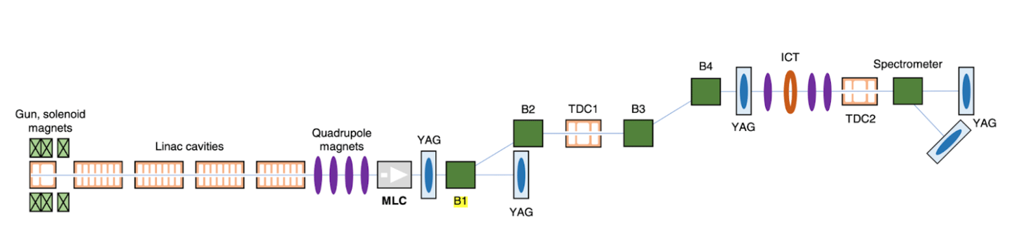
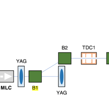
Figure 1. Schematic of AWA drive linac and EEX beamline (not to scale)
A key obstacle in wakefield acceleration is the improvement of energy transfer efficiency, which is roughly measured by a benchmark known as the 'transformer ratio'. For applications like beam-driven wakefield acceleration, asymmetric drive beam current profiles with a ramped rising edge followed by a rapid termination can be used to overcome the transformer ratio limitation of 𝑅<2 for symmetric bunches. Even higher transformer ratios can be accessed by optimizing the drive beam head region with features like doorstep or parabolic profiles [2]. Plasma wakefield acceleration (PWFA) utilizes the immense electrostatic fields that can be excited in the wake of a relativistic particle bunch propagating through a plasma. These wakefields have shown the ability to sustain accelerating gradients well in excess of 10 GeV/m, several orders of magnitude higher than conventional radio-frequency accelerators. Harnessing these ultra-high gradients could enable extremely compact, high-energy particle accelerators for a wide range of applications. However, a key challenge in realizing the full potential of PWFA is maximizing the efficiency of energy transfer from the intense drive bunch to the trailing witness bunch being accelerated. This transfer efficiency is quantified by the transformer ratio 𝑅, defined as the ratio of the maximum accelerating field experienced by the witness (𝑊+) to the maximum decelerating field acting on the drive bunch (𝑊−):
𝑅=|𝑊+|/|𝑊−|
For highly symmetric drive bunches like Gaussian or semi-Gaussian distributions, linear wakefield theory imposes a fundamental limit of 𝑅<2. To overcome this limit and enable higher energy gain, precisely tailored asymmetric drive bunch profiles must be used to shape the wakefield. One class of drive bunch shapes predicted to enhance the transformer ratio are linearly ramped distributions, with a long leading ramp followed by a rapid current termination. Further theoretical work by Lemery and Piot [3] extended this concept by introducing more elaborate driving profiles. By modifying the linear ramp to include specific head features like a "doorstep" or parabolic upramp, the region of uniform deceleration inside the drive bunch can be extended. This increases the effective beam-loaded acceleration length and enables transformer ratios up to 𝑅≈6, even within the linear PWFA regime. While these tailored asymmetric bunches improve energy transfer, generating such specialized drive beam distributions has proven challenging. Some techniques employed include developing precise phase space correlations using higher-order optics, driving self-wakefield modulations in dielectric structures, or direct laser shaping at the photocathode source. However, these methods face limitations in the charge regimes accessible, the level of control over fine bunch features, or the overall driver complexity. The use of EEX beamlines has emerged as a powerful tool for flexible longitudinal bunch shaping via the mapping of the transverse phase space coordinates onto the longitudinal dimension. In the EEX process, a particle's initial transverse coordinate (𝑥,𝑥′) is transformed to a new longitudinal position 𝑧_𝑓 according to:
𝑧_𝑓 = (𝐴 + 𝐵𝑆)𝑥_𝑖
Where 𝐴,𝐵 are coefficients determined by the EEX optics, like dispersion and longitudinal compression, and 𝑆 represents the transverse phase space slope [4]. S = 𝑑𝑥'/𝑑𝑥 By shaping the beam's horizontal profile before the EEX beamline using a mask or collimating slit, one can imprint that transverse distribution onto the longitudinal current profile after the exchange. Leveraging EEX, several experiments have successfully generated high-charge bunches with ramped, doorstep, and other asymmetric current profiles optimized for PWFA drive beams. To efficiently explore the potential of tunable EEX-based bunch shaping for optimizing transformer ratios, we have developed a novel multi-leaf collimator (MLC) capable of operating in ultrahigh vacuum environments [5]. The MLC comprises numerous independently actuated leaves that intersect the beam's trajectory, facilitating the formation of a customized aperture (Figure 2). Predominantly utilized in radiotherapy [6–8], MLCs meticulously contour the radiation beam to conform to the target's geometry from various angles, ensuring efficient dose administration while minimizing radiation exposure to surrounding non-target areas. Within an EEX beamline framework, the MLC provides swift and versatile manipulation of both the drive and witness beam current profiles and their separation. This report elaborates on the contributions made towards the development and prototyping of the MLC as part of a contract course (Phys 199). Our efforts are delineated into a series of phases—development of simulation pipeline, benchmarking, beam shaping validation, simulation of the second MLC prototype, and performance optimization.
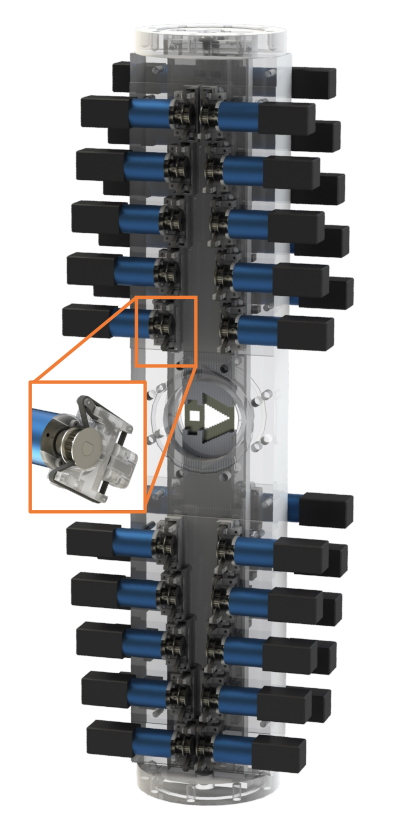
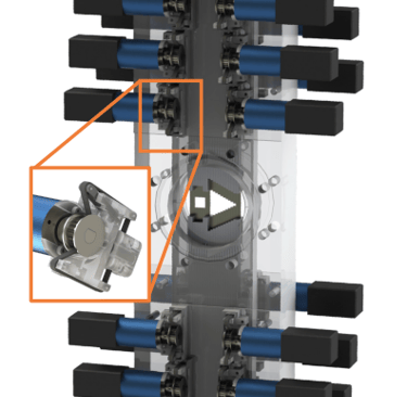
Figure 2. A visualization of the multileaf collimator, alongside the vacuum chamber and select support structures rendered translucent for clarity, depicts the creation of a mask for both a ramped drive beam and a witness beam
2. Development of Simulation Pipeline
Work began with the creation of a detailed simulation pipeline using the Object-Oriented Particle Accelerator Library (OPAL). OPAL is a sophisticated simulation tool specifically designed for modeling the dynamics of particle accelerators and beam lines. This phase entailed integrating a model of the AWA’s EEX beamline into an OPAL simulation environment. We crafted scripts to simulate the MLC in a variety of configurations, alongside scripts for data extraction, analysis, and visualization to confirm the accuracy of our simulation outcomes. We integrated a precise simulation model of the AWA EEX beamline, sourced from AWA collaborator Seongyeol Kim. This integration was pivotal for advancing the simulation capabilities pertaining to the MLC. A specialized set of Python scripts was designed for the dual purpose of generating bitmap files and their corresponding PNG images. These files delineate the configuration of the MLC within the simulation, instructing OPAL to selectively eliminate particles upon their simulated interaction with the MLC, thus achieving the desired beam shaping effect. Additionally, a systematic workflow was established to analyze the resultant phase space of all particles within the simulation (Figure 3). This involved extracting essential data from the simulation outputs and generating plots of distributions that are of particular relevance to the study of PWFA. Specifically, plots of the longitudinal distribution of the beam for PWFA and the distribution at the mask are generated for the purpose of verifying that the beam is indeed being shaped by the MLC at the mask step. These plots play a crucial role as they visually demonstrate the influence of the MLC on the beam, serving as a foundation for designing our experiments based on the simulations. Additionally, they are instrumental in interpreting our data, allowing us to align our experimental findings with the predicted beam dynamics for advanced accelerator applications.
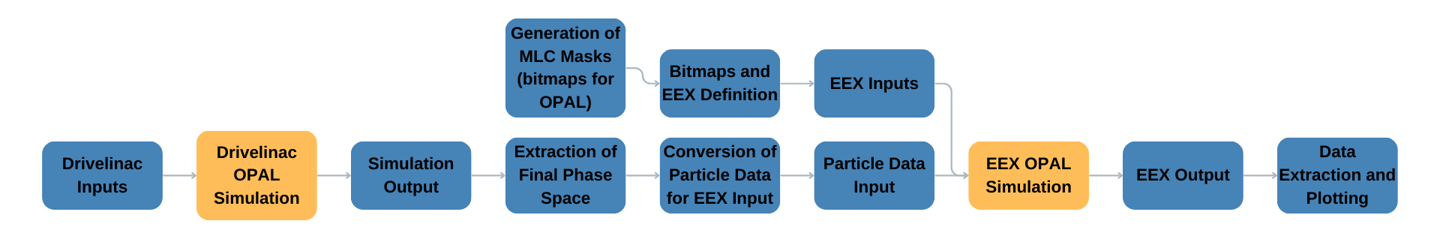
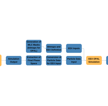
Figure 3. Basic simulation workflow utilizes a simulation of the drivelinac (up until the MLC) followed by a simulation of the rest of the beamline (EEX, from the MLC and onwards)
3. Benchmarking
The second phase of the project focused on benchmarking the simulation pipeline to validate its credibility and the accurate modeling of the MLC within the EEX beamline environment. Initial benchmarking efforts were centered around the implementation of a null mask scenario—essentially, a simulation configuration wherein the MLC was not introduced, thereby precluding any beam shaping. This scenario was predicated on the expectation that the beam, solely influenced by the initial quadrupoles of the drive linac, would maintain its configuration through to the mask step without alteration, thereafter evolving in accordance with the principles of EEX transformation. The outcomes of this simulation run, which aligned with the anticipated results, depicted a collimated beam undergoing the EEX transformation unaltered (Figure 4).
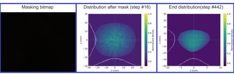
Figure 4. Plots of particle distributions resulting from the null mask, shown as overlayed normalized density heat map and normalized density distribution as function of x and y after the MLC and as function of x and z after EEX transformation.
Subsequent benchmarking exercises introduced a square mask configuration within the simulation. This was anticipated to result in a square beam distribution immediately following the beam shaping by the MLC, with the expectation of observing a shaped distribution characterized by hard edges in the longitudinal profile post-EEX transformation. The findings from this simulation (See Figure 5), corroborated these expectations, showcasing the precise influence of the square mask on the beam's configuration.
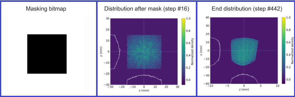
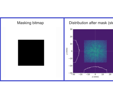
Figure 5. Distributions resulting from a square shaped test mask.
Further validation of the simulation pipeline's efficacy was conducted through a simulation of a drive and witness beam configuration, a scenario typical of wakefield acceleration applications. This simulation aimed to replicate a complex beam shaping scenario, anticipating distinctive alterations in the beam profile attributable to the specific MLC mask shape. The results (See Figure 6), provided conclusive evidence of the simulation's capability to accurately model the effects of the MLC mask on the EEX beam distribution. These initial benchmarking efforts served as a foundational validation, confirming the simulation pipeline's accuracy and reliability for future testing and experimental correlations.
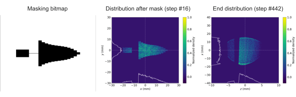
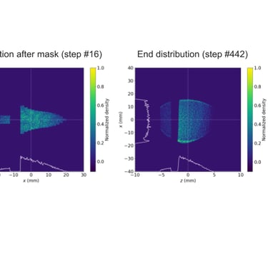
Figure 6. Distributions resulting from a PWFA beam shaping mask
4. Verification of Beam Shaping Capability for Arbitrary MLC Mask Shape
Building on the verified core principles from previous simulation work, the project advanced to investigate the MLC's capability for producing arbitrary beam shapes through diverse configurations. This phase aimed at rigorously testing the MLC's flexibility and precision in beam shaping, essential for tailoring beam profiles for various experimental requirements in wakefield acceleration and other advanced accelerator applications. The key step in this exploration was the design and implementation of tunable Python scripts capable of modeling the MLC in arbitrary configurations. These scripts generated bitmap files used by OPAL to define the beam mask. Special attention was given to ensuring that the generated bitmaps replicated the physical characteristics of the MLC, including the resolution and specific attributes of its leaves. The MLC leaves, each 2 mm wide, can create "pixelated" masks that approximate continuous shapes to a degree determined by the MLC's physical resolution and operational mechanics. This capability allows for nearly arbitrary shaping of the beam profile, accommodating the experimental specifics outlined in previous studies. Subsequent tests provided further validation of the MLC's arbitrary shaping capability. Simulation runs included scenarios with single leaves in both open and closed positions, as well as custom shapes designed to test the MLC's versatility. The outcomes, illustrated below (Figure 7), showcase the MLC's robustness in creating a wide array of beam profiles.
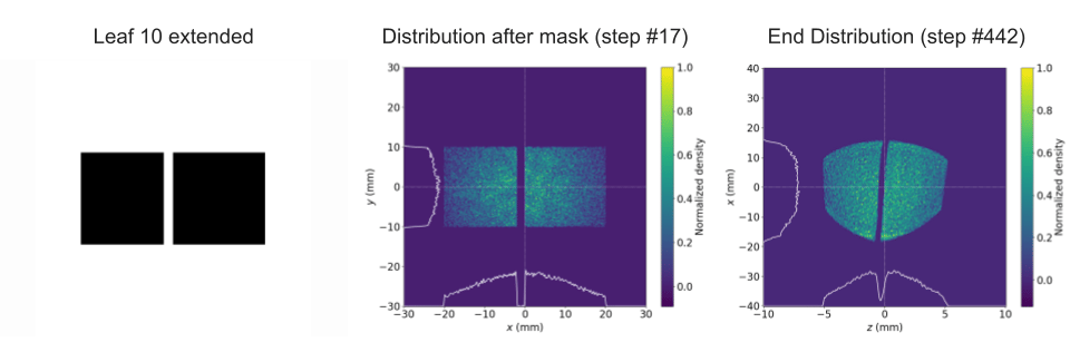
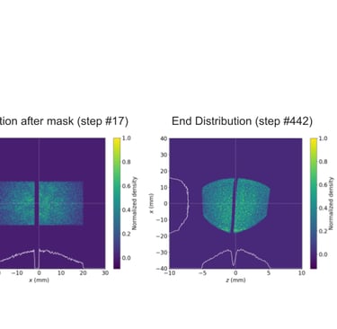
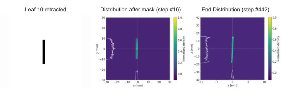
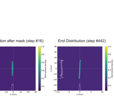
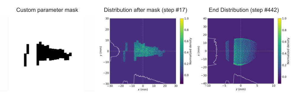
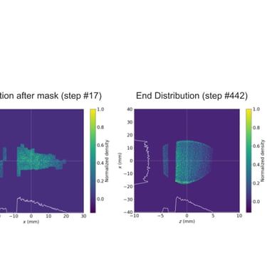
Figure 7. (top). Distributions from full aperture open except a single leaf (leaf 10) extended. (middle). Distributions from closed MLC with a single leaf (leaf 10) retracted permitting only a thin band to pass. (bottom). Distributions from a discontinuous variation on a drive and witness beam configuration, testing the flexibility of the MLC. The ability of the pipeline to generate arbitrary configurations of the MLC and the response to variations on typical PWFA beam shapes.
5. Modeling and Simulation of the Second Prototype
In the progression towards enhancing the MLC operational robustness and reliability, a pivotal phase involved the development and simulation of a second prototype. This iteration was aimed at addressing and mitigating the challenges observed with the magnetic coupling mechanism used in the first prototype, specifically designed to operate under the ultra-high vacuum conditions of the beamline. The magnetic coupling, while innovative, had shown vulnerabilities, particularly in the risk of decoupling, which could lead to operational downtime. Additionally the rotational motion of the updated MLC design involves fewer moving parts, reducing the device’s number of failure points significantly. To counter these challenges, the second prototype introduced a novel design feature: grooved rotating leaves, which replaced the previously used actuating tungsten teeth. This design modification aimed to significantly enhance the device's durability and operational reliability. The simulation of this updated MLC involved representing the device as a collection of vertical slices, simulating a three-dimensional configuration through strategically spaced and shaped 2D mask elements. This approach allowed for a more detailed and accurate modeling of the MLC's functionality, reflecting the grooved leaves' unique interaction with the particle beam. The specifications for the MLC version 2 were detailed (Figure 8), incorporating a Z gap of 50 µm (the distance between consecutive 2D masks), a total mask count of 41 (forming a stack along the beamline, with each mask separated by 50 µm), and a leaf count of 52 (26 upper and 26 lower leaves). The leaves were designed with a width of 1.8 mm and featured an X gap of 0.1 mm (the empty space between adjacent leaves), a leaf throw of 26 mm (the maximum dynamic range for leaf movement), and a Y gap of 0.1 mm (the gap between the top and bottom row of leaves when fully extended).
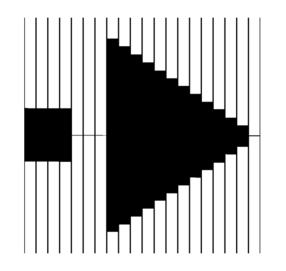
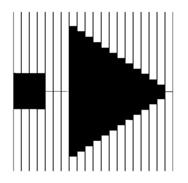
Figure 8. Example mask showing the characteristic features of the MLC version 2.
Given the nuanced design of the grooved leaves, which did not present a flat surface to the particle beam, the interaction between the particles and the mask occurred at slightly different times depending on the particles' positions. This aspect prompted a thorough investigation into how a three-dimensional model of the MLC would perform compared to a simplified 2D approximation, particularly in terms of beam shaping efficacy. Initial benchmarking efforts aimed to verify the feasibility and effectiveness of simulating a three-dimensional mask using discrete 2D slices. These benchmarks confirmed that a 3D mask maintained the capability to shape beams as effectively as its predecessors (Figure 9). However, during further testing of the MLC version 2's 3D model, initial benchmarks were not met due to a simulation anomaly that allowed for unintended particle bleed-through—a phenomenon that should have been prevented by the mask (Figure 9). This issue was traced back to a flaw in OPAL's rasterization process, which overlooked portions of the mask. This discovery led to collaboration with the developers, resulting in a software patch that rectified the identified issues.
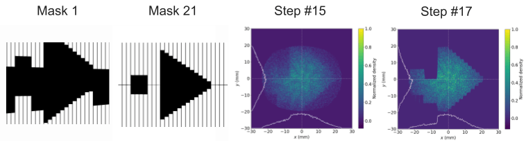
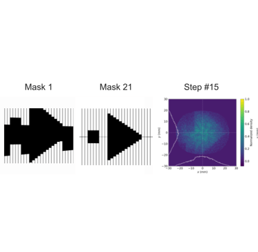
Figure 9. (top) 3D mask stack test, a demonstration meant to show that the distribution takes the shape of the sum of discrete masks. (bottom) Distributions after run through the 41 mask stack modeling the version 2 MLC. Shapes of masks 1 and 21 shown here. These results show the evolution of the beam shape as it passes through the masking layers. The aforementioned error is present in these results, the bleedthrough of particles can be seen in quadrant 4 and precludes the separation of the drive and witness beams.
With the 3D MLC version 2 simulation validated, comparisons were drawn between this model and a 2D version of the same prototype. While both models yielded comparable results, the 3D version's fidelity to real-world conditions underscored its significance, especially in light of subsequent phases focusing on orientation optimization. Therefore, the project proceeded with the 3D model of MLC version 2 as the standard for future simulations and experimental setups, laying a robust foundation for the next phase of optimization and refinement.
6. Determining the Optimal Orientation of the MLC
In the fifth phase of the project, the focus shifted towards optimizing the MLC’s orientation to address a specific operational challenge: the bleed-through of particles. This phenomenon was observed due to the 1mm gaps between the leaves, which, under certain conditions, allowed particles to pass through, thereby affecting the particle distributions. This issue manifested as thin vertical bands of particles in the beam profile, an artifact that undermined the MLC's ability to precisely control the beam shape. Recognizing that a minor adjustment in the MLC's orientation could potentially address this problem, the team hypothesized that a slight rotation of the MLC would render the mask opaque to these stray particles, effectively eliminating the unwanted banding. To test this hypothesis, a series of simulations were conducted with the MLC rotated at different angles: 2 degrees, 1 degree, and 0 degrees. The objective was to identify the minimal degree of rotation necessary to achieve the desired effect without compromising the overall functionality of the MLC. The results of these simulations provided clear evidence that rotating the MLC by just 1 degree was sufficient to eliminate the banding effect observed in the beam profile, as demonstrated (Figure 10) This finding was significant as it offered a straightforward and effective solution to enhance the MLC's beam shaping capabilities, ensuring that the MLC could maintain tight control over the beam profile without the degradation caused by particle bleed-through.
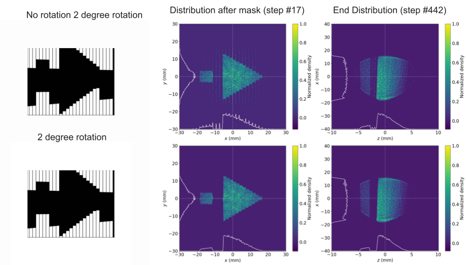
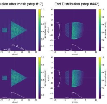
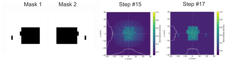
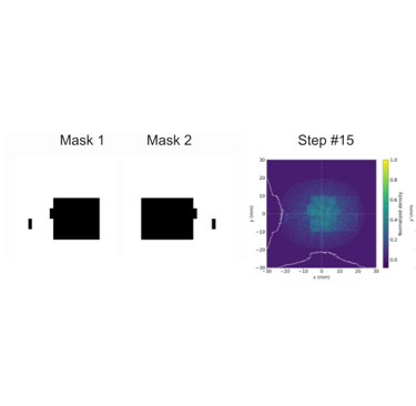
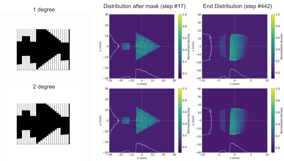
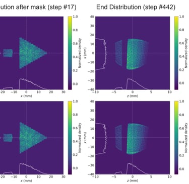
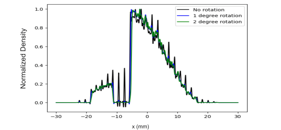
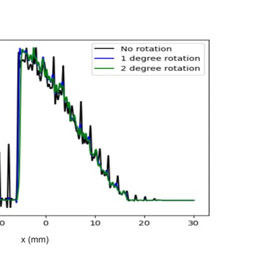
Figure 10. (top) Comparison of the unrotated MLC and MLC with 2 degree rotation, the former shows leakage in the form of vertical bands while the rotation eliminates the banding by closing the apparent gaps between individual leaves. (middle) The 2 degree and 1 degree rotations are compared, both eliminate leakage. (bottom) The longitudinal distributions for each orientation are overlaid in a plot of normalized density vs position. Both 1 and 2 degree rotation eliminate the banding leakage (characterized by spikes along the distribution). A 1 degree rotation is taken to be the minimum viable orientation for mitigating leakage.
7. Optimizing the Drive Linac
In the project's final phase, we faced the prospect of needing to remove one of the four focusing quadrupoles to accommodate the physical installation of the MLC's final version. This prompted an essential optimization process to ascertain the viability of such a modification without compromising the MLC's beam shaping capabilities and the overall integrity of the EEX process. Through this optimization, we aimed to ensure that the remaining three quadrupoles could effectively maintain beam focus and stability, thereby safeguarding the MLC's functionality in precise beam shaping. Initial simulations indicated that the removal of a quadrupole significantly altered the beam distribution following the EEX, adversely affecting the beam shaping capabilities (Figure 11). This finding underscored the need for an optimization strategy to correct the beam profile.
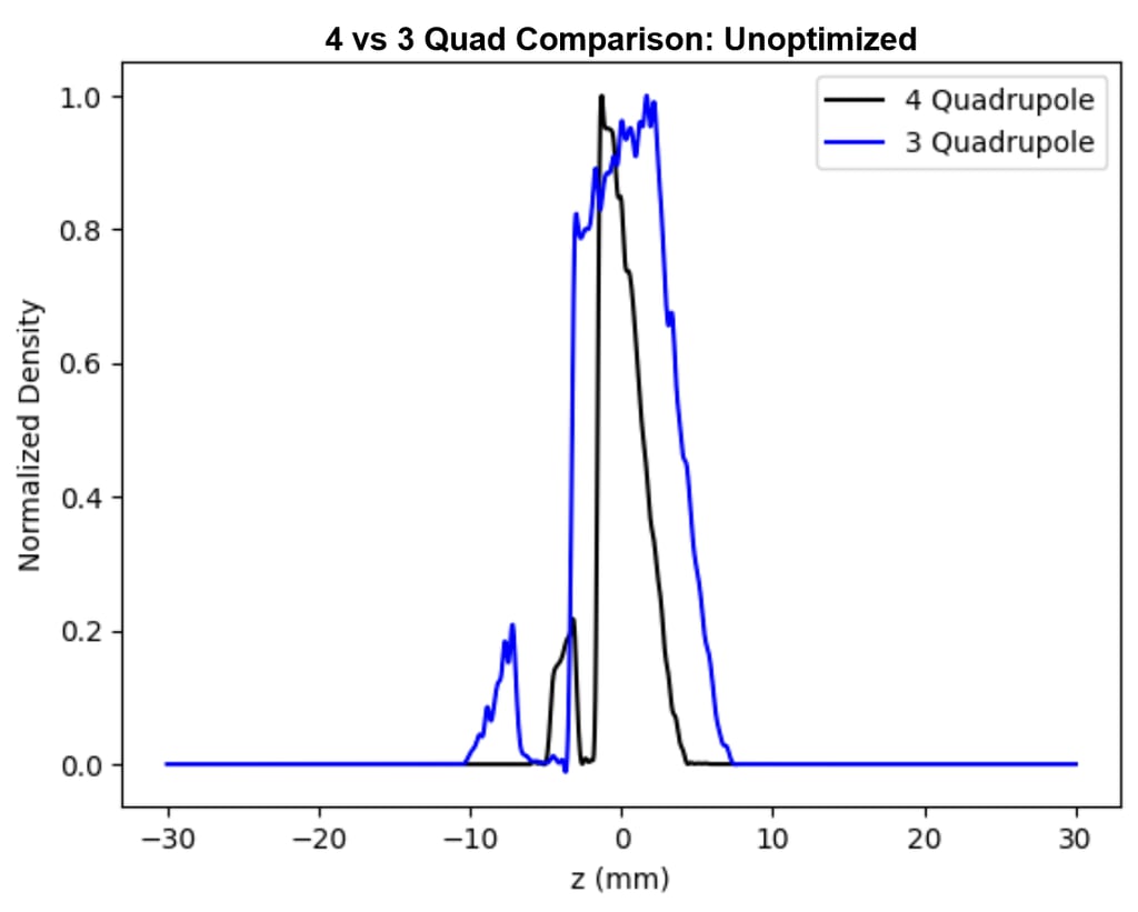
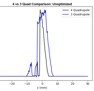
Figure 11. The unoptimized comparison of normalized density vs z from previous benchmarks and after the removal of the fourth quadrupole.
The optimization then, aimed at minimizing transverse momentum (𝑝 ) to ensure the particle 𝑥 beam remained focused and did not diverge upon interacting with the MLC. The strength of the remaining three quadrupoles was varied systematically and searched over using OPAL’s built in optimization tools. By focusing on minimizing the absolute value of the root mean square of the transverse momentum (rms_px') at the initial mask location of the MLC, and adjusting the strength of the remaining three quadrupoles, we were able to restore the desired beam profile, closely aligning with our simulation predictions (Figure 12).
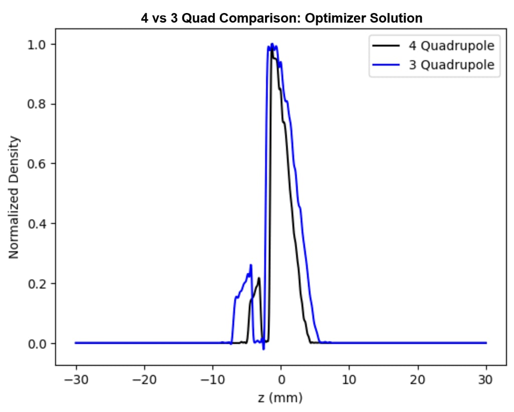
Figure 12. Comparison of final distributions (normalized density vs z) for original 4 quadrupole benchmark and Initial optimization results with 3 quadrupoles.
With the established simulation pipeline, there's substantial scope for further optimization through more sophisticated use of tools like the OPAL optimizer and machine learning techniques. These resources offer an avenue for in-depth exploration of how the MLC can be leveraged in wakefield acceleration experiments. The potential for this exploration extends to employing optimization strategies to find MLC configurations tailored to achieving specific beam distribution profiles. Such advancements could enhance the precision and effectiveness of beam shaping. Anticipated future work with PBPL in a contract course this Spring aims to harness these tools, setting the stage for developments in beam manipulation and control strategies.
References
[1] G. Ha, M. Conde, D. Doran, J. Power, V. R. W. Schaa, G. Arduini, J. Pranke, M. Seidel, M. Lindroos, “Limiting Effects in the Double EEX Beamline,” in Proc. of the [Conference Name] (2017).
[2] K. L. Bane, P. Chen, and P. B. Wilson, “Collinear wake field acceleration,” Tech. Rep. (Stanford Linear Accelerator Center, 1985).
[3] F. Lemery and P. Piot, "Tailored electron bunches with smooth current profiles for enhanced transformer ratios in beam-driven acceleration," Submitted on 22 May 2015.
[4] Roussel, R., Andonian, G., Lynn, W., Sanwalka, K., Robles, R., Hansel, C., Deng, A., Lawler, G., Rosenzweig, J.B., Ha, G., Seok, J., Power, J.G., Conde, M., Wisniewski, E., Doran, D.S., & Whiteford, C.E., "Single-Shot Characterization of High Transformer Ratio Wakefields in Nonlinear Plasma Acceleration," arXiv:1910.08601v1 [physics.acc-ph] (2019).
[5] N. Majernik et al., "Beam shaping using an ultra-high vacuum multileaf collimator and emittance exchange beamline," arXiv:2210.02572 [Online]. Available: https://arxiv.org/abs/2210.02572 (2022).
[6] T. J. Jordan and P. C. Williams, "The design and performance characteristics of a multileaf collimator," Physics in Medicine & Biology 39, 231 (1994).
[7] A. L. Boyer, T. G. Ochran, C. E. Nyerick, T. J. Waldron, and C. J. Huntzinger, "Clinical dosimetry for implementation of a multileaf collimator," Medical Physics 19, 1255 (1992).
[8] Y. Ge, R. T. O’Brien, C.-C. Shieh, J. T. Booth, and P. J. Keall, "Toward the development of intrafraction tumor deformation tracking using a dynamic multi-leaf collimator," Medical Physics 41, 061703 (2014)